Banner Image

X5 preamp power

pomonabill220

New member
Hello All!
I wanted to know if there is a way to have my X5 phono preamp power on when the AC adapter is powered on?
I don't want to leave it on all the time, but when I power up my main system, I would like the preamp to power up also without having to press the power button.
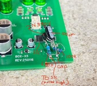
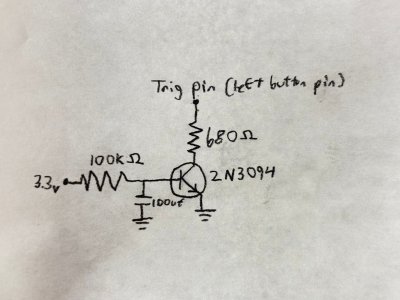
I could make a momentary pulse circuit using a timer and relay to "simulate" the power button, but just wanted to know if there was a way to do this with maybe a jumper in the preamp itself.
Thanks!
Bill
 
I have a simmilar issue. Planning on using a normally closed transistor (or relay) then using power inside the unit to bring the transistor open. The X5 seems to power up on power button press, not release, so this can work. I will update here when I finish it.
 
I have a simmilar issue. Planning on using a normally closed transistor (or relay) then using power inside the unit to bring the transistor open. The X5 seems to power up on power button press, not release, so this can work. I will update here when I finish it.
That is true ...BUT
The power needs to be applied FIRST BEFORE the button is "pushed" as the processor needs to boot up first THEN it will respond to the button press, which pulls the processor's input to ground and is pulled up to 3.3VDC through a 10K resistor.
So a delay between power up and button press needs to happen for about 1-2 seconds.
 
Yes, figured that out when I diagnosed it further. I got it working with an RC delay timer into an NPN to pull it low. It seems like it can stay low while it is on, in the program they are probably waiting for the button to go high again before checking for subsequent button presses. I have the circut in IMG_2043, and a drawing of it in IMG_2045. In IMG_2044 there is a 3.3v post-powerup source that I was going to run to the trig pin (left button pin / pin 7 of STC) to bring it high again, but it seems like another RTC circut is needed here for this to work properly. There is another 3.3v post-powerup source at the top middle of the board comng from pin 2 of the STC... but again, it seems like it can stay low while it is on.

I am planning on putting mine in a jukebox so I can convert the cartride over to MM from the original Sonotone 8TA ceramic. I need the preamp to powerup when the jukebox does since I cant open it. They really should have used a switch here instead of a button.
 

Attachments

  • IMG_2043.jpeg
    IMG_2043.jpeg
    445.4 KB · Views: 2
  • IMG_2044.jpeg
    IMG_2044.jpeg
    324.3 KB · Views: 2
  • IMG_2045.jpg
    IMG_2045.jpg
    1.3 MB · Views: 2
Yes, figured that out when I diagnosed it further. I got it working with an RC delay timer into an NPN to pull it low. It seems like it can stay low while it is on, in the program they are probably waiting for the button to go high again before checking for subsequent button presses. I have the circut in IMG_2043, and a drawing of it in IMG_2045. In IMG_2044 there is a 3.3v post-powerup source that I was going to run to the trig pin (left button pin / pin 7 of STC) to bring it high again, but it seems like another RTC circut is needed here for this to work properly. There is another 3.3v post-powerup source at the top middle of the board comng from pin 2 of the STC... but again, it seems like it can stay low while it is on.

I am planning on putting mine in a jukebox so I can convert the cartride over to MM from the original Sonotone 8TA ceramic. I need the preamp to powerup when the jukebox does since I cant open it. They really should have used a switch here instead of a button.
Looks good!
Yes, that will turn the preamp on after the 100k/100uF charges up and turns on the transistor.

Just to be on the safe side, I would parallel the 100K with a diode, anode on the 100uF cap and cathode on the 3.3v line.
That would discharge the cap when 3.3v goes away.
That would keep the base/emitter of the transistor conducting and dumping the cap's charge onto the ST's input, which might damage the ST or at least toast the input.

The base/emitter junction would look like a forward biased diode when the base is higher than the collector.

Just a thought!
 
Another thought.....
IF you were to use a FET rather than a transistor, your capacitor value could be about 100X smaller and you wouldn't have to worry about forward biasing the transistor as a FET is not a junction device.
Just another thought.
 
Back
Top